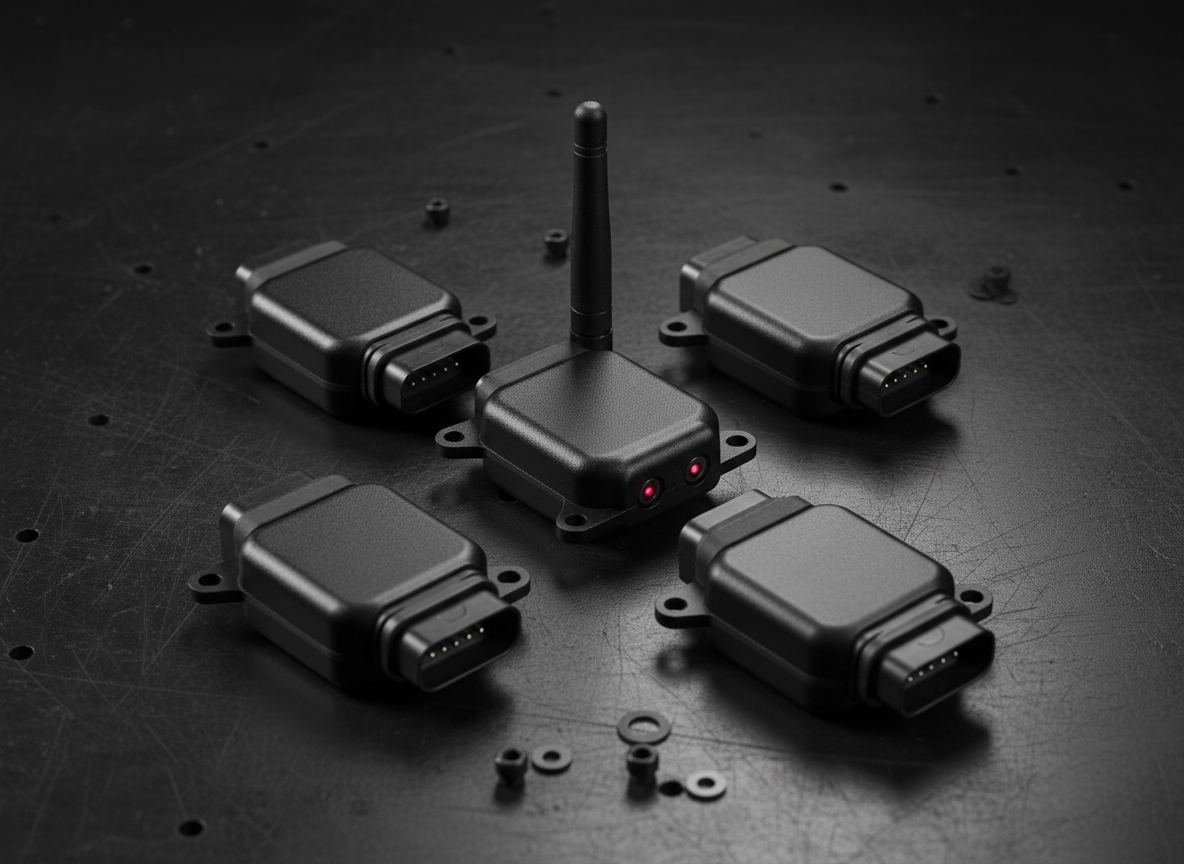
SYSTEM ARCHITECTURE / FUTURE IGNITION
Wireless sensing.
Hardwired control.
Low-power nodes report wirelessly to the central hub. The planned ignition module connects directly to engine-critical circuits, executes timing locally, and shares configuration and telemetry over the NodeIQ network.
THREE LAYERS
01 / Leaf Nodes
Battery-powered while riding. Preferred baseline: CC2340-class ultra-low-power MCU/radio using raw IEEE 802.15.4 in a star network.
Candidate roles include IMU, RPM/speed interface, tire pressure, fuel-level interface, and other non-timing-critical sensing.
02 / Main Hub
An ESP32-C6 coordinates sensor traffic, aggregates ride data, and acts as the only routine phone-facing endpoint.
BLE/Wi-Fi stay at the hub. Leaf nodes avoid Wi-Fi to protect the power budget.
03 / NodeIQ App
The Android app discovers the system, manages nodes, records rides, presents telemetry, and exposes connectivity and battery diagnostics.
Current prototype path: IMU ESP32 → GPS ESP32 gateway → phone.
FLAGSHIP INTEGRATION / IGNITION CONTROL
The spark stays local. The intelligence travels.
The ignition module is a hardwired, deterministic controller with a wireless relationship to the central hub. The hub and app can commission the system, move validated maps, and observe operation, but they never schedule an individual spark.
Hardwired control
Power and ground, crank or cam trigger inputs, coil or ignition outputs, local dwell control, and microsecond-level event scheduling.
Automatic detection
Identify cylinder count, trigger pattern, edge polarity, synchronization behavior, and a compatible baseline configuration for installer verification.
Wireless intelligence
Send RPM, commanded advance, dwell, sync state, faults, and map version to the hub; receive guarded configuration and map updates.
Adjustable maps
RPM-and-load timing tables, selectable profiles, comparison tools, bounded edits, staged application, version history, and rollback.
Local fallback
Continue on a validated last-known-good map if the hub or phone disconnects. Invalid or incomplete configurations do not enter service.
Installer verification
Automatic detection proposes a setup; base timing, trigger alignment, coil compatibility, and operating limits still require qualified confirmation.
POWER & WIRING STRATEGY
Two conductors for sensors. Dedicated wiring for ignition.
CHG+ and CHG− form a shared charging backbone for remote sensor nodes. The ignition module is different by design: it remains hardwired to vehicle power, trigger inputs, and ignition outputs while communicating wirelessly with the hub.
| Sensor nodes | Battery-powered while riding | Wireless telemetry |
| Ignition module | Vehicle-powered and hardwired | Local spark control |
| Central hub | Network coordinator | Configuration and aggregation |
| Phone link | Hub only | App, maps, and diagnostics |
Future integration families
Motion
IMU orientation, lean, acceleration, vibration, and road-quality sensing.
Powertrain
Ignition timing, RPM, dwell, synchronization, and fuel-level interfaces.
Chassis
Tire pressure, speed, brake events, switch inputs, and additional isolated sensors.
Navigation & health
GPS route, charging state, batteries, signal strength, and network diagnostics.
Current status
The distributed sensing architecture is defined. The ignition system is a future-development architecture, not validated production hardware. Trigger decoding, automatic engine detection, timing and dwell accuracy, coil protection, map safeguards, electrical-noise tolerance, and fail-safe behavior require staged bench, dyno, and road testing.
 NodeIQ